Johdanto
Liikkuvissa koneissa – mukaan lukien kaivinkoneet, pyöräkuormaaja, maatalousharvesterit ja metsäkoneet – hydraulineste toimii ensisijaisena energiansiirron väliaineena. Erillisten roolien ymmärtäminenhydraulinen paine($P$) jahydraulinen virtausnopeus($Q$) ja niiden matemaattinen vuorovaikutus ovat välttämättömiä tehokkaiden, luotettavien ja reagoivien liikkuvien hydraulijärjestelmien suunnittelussa.
Yleinen väärinkäsitys ei-ammattilaisten keskuudessa on paineen rinnastaminen tehoon tai virtausnopeuden sekoittaminen voimaan. Nestevoimamekaniikassapaine määrää voimantuoton, kun taasvirtausnopeus määrää toimilaitteen nopeuden. Paineen ja virtausnopeuden tulo määrittää kokonaishydraulisen hevosvoiman tai kilowattikapasiteetin.
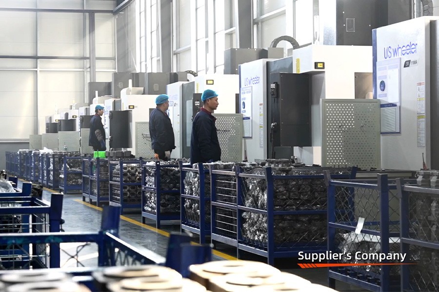
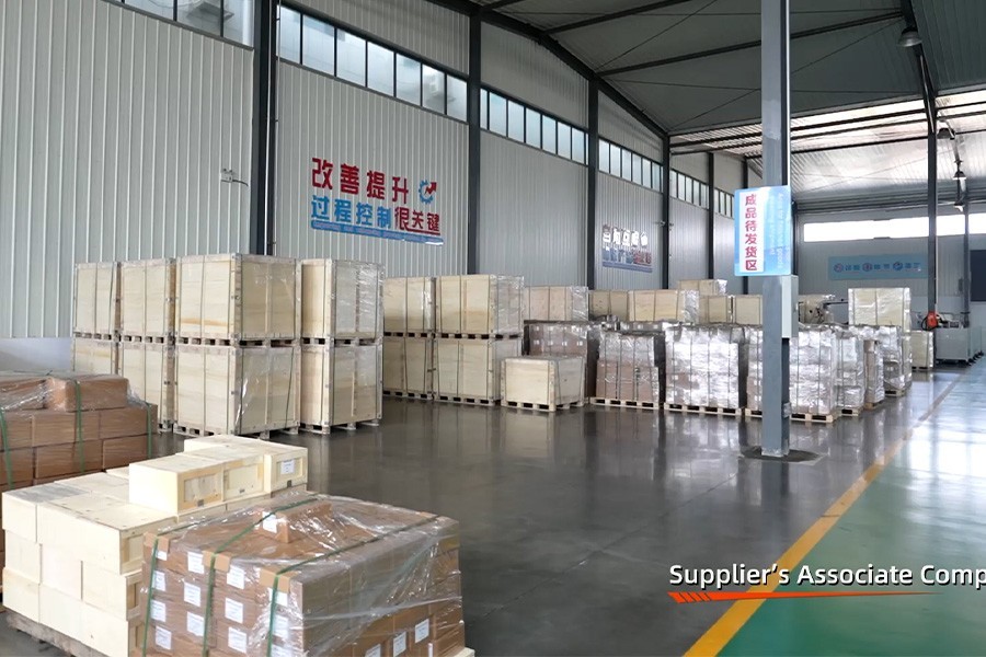
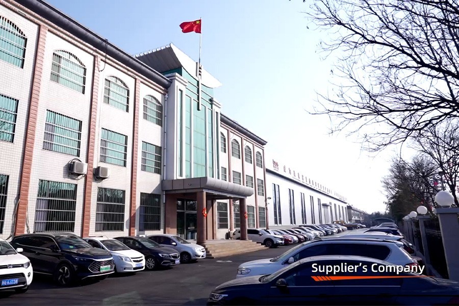
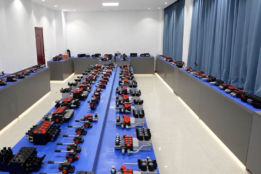
Boxinhuasheng Hydraulic Technology Co., Ltd.:ssä insinööritiimimme tekee tiivistä yhteistyötä maailmanlaajuisten alkuperäislaitteiden valmistajien (OEM) kanssa optimoidakseen nesteen tehon reitityksen suuntaventtiilien, hammaspyöräpumppujen ja voimanoton (PTO) välillä. Vuonna 2001 perustettu Boxinhuasheng operoi 68 000 m²:n kampuksella, jota tukevat 35 vanhempaa hydrauliinsinööriä ja yli 30 automatisoitua testauspenkkiä, jotka on sertifioitu IATF 16949 -standardien mukaisesti.
Tämä artikkeli tarjoaa teknisen oppaan liikkuvien koneiden hydraulivirtauksen ja paineen dynamiikkaan, joka kattaa hallitsevat yhtälöt, painehäviön minimoinnin, lämmönhallinnan ja käytännön venttiilien mitoitusperiaatteet.
Perusfysiikka: paine vs. virtausnopeus
Liikkuvien hydraulipiirien analysoinnissa insinöörit luottavat fyysisiin ydinsuhteisiin, jotka säätelevät nesteen painetta, mekaanista voimaa, tilavuusvirtausta ja toimilaitteen nopeutta.
+--------------------------------------------------------------------------+
|                  YDINHYDRAULISET OHJAUKSET |
+---------------------------------------------------+------------------------+
| Hydrauliparametri | Hallitseva kaava | Muuttujien määritelmät |
+---------------------------------------------------+------------------------+
| Mekaaninen voima ($F$) | $F = P \cdot A$ | $P$ = Paine (Pa), |
|                          |                       | $A$ = porausalue ($m^2$)|
| Toimilaitteen nopeus ($v$) | $v = \frac{Q}{A}$ | $Q$ = Virtausnopeus ($m^3/s$)|
| Hydraulivoima ($kW$) | $P_{kW} = \frac{P \cdot Q}{600 \cdot \eta}$ | $P$ baarissa, $Q$ L/min, |
|                          |                       | $\eta$ = tehokkuus |
+---------------------------------------------------+------------------------+
#### 1. Hydraulipaine ($P$)
Painetta syntyy, kun nestevirtaus kohtaa vastuksen (kuten hyötykuorman painot, mekaaninen kitka tai linjarajoitukset). Mobiilijärjestelmissä:
- Nimellinen työpaine: Tyypillisesti vaihtelee välillä 16 MPa - 31,5 MPa (160 - 315 bar).
- Huippuiskun paine: Kauhan törmäyksen tai äkillisen venttiilin sulkeutumisen aiheuttamat hetkelliset painepiikit voivat ylittää nimellispaineen 40-50 %, mikä vaatii korkean lujuuden pallografiittiraudan (QT500-7) venttiilikotelot.
#### 2. Hydraulinen virtausnopeus ($Q$)
Virtausnopeus edustaa syrjäytyneen nesteen tilavuusmäärää aikayksikköä kohti, mitattuna litroina minuutissa (L/min) tai galloneina minuutissa (GPM):
- Pumpun iskutilavuus: $Q_{pumppu} = \frac{V_d \cdot n \cdot \eta_v}{1000}$, missä $V_d$ on pumpun iskutilavuus ($cm^3/kierros$), $n$ on moottorin kierrosluku ja $\eta_v$ on tilavuushyötysuhde.
- Toimilaitteen nopeus: Pumpun iskutilavuuden kaksinkertaistuminen kaksinkertaistaa sylinterin pidennysnopeuden muuttamatta tehoa.
Painehäviöt ($\Delta P$) ja nesteen tehohäviö
Kun hydrauliöljy virtaa suuntasäätöventtiilien, letkujen, liitosten ja jakoputkien läpi, nestekitka aiheuttaa paikallisia painehäviöitä ($\Delta P$).
Korkeapaineinen öljy sisään (P-portti) ──► sisäinen mittausaukko (ΔP) ──► alennettu paine työportissa (A)
                                           │
                                  Kitkaenergiahäviö ──► muunnetaan lämmöksi (kW)
Aukon virtausyhtälö kuvaa, kuinka painehäviö liittyy virtausnopeuteen venttiilikelan loven poikki:
$$Q = C_d \cdot A_o \cdot \sqrt{\frac{2 \cdot \Delta P}{\rho}}$$
Jossa:
- $C_d$ = Purkauskerroin (~ 0,60 - 0,62)
- $A_o$ = Aukon aukkoalue ($m^2$)
- $\Delta P$ = Painehäviö venttiilin pinnassa ($Pa$)
- $\rho$ = Nesteen tiheys ($kg/m^3$)
#### Energiahäviöt ja lämmönhallinta
Painehäviö, joka ei tee hyödyllistä mekaanista työtä, muunnetaan suoraan lämpöenergiaksi:
$$P_{lämpö (kW)} = \frac{\Delta P (bar) \cdot Q (L/min)}{600}$$
Esimerkiksi siirrettävä kuormaaja, joka toimii 20 baarin painehäviöllä alimittaisen suuntaventtiilin yli nopeudella 100 l/min3,33 kW jatkuvaa hukkalämpöä. Täyden työvuoron aikana tämä lämpökuorma nostaa hydrauliöljyn lämpötiloja, alentaa öljyn viskositeettia, nopeuttaa tiivisteen rikkoutumista ja lyhentää pumpun käyttöikää.
Paineenalennusventtiilin dynamiikka mobiilipiireissä
Pumppujen, sylintereiden ja rakennepuomien suojaamiseksi rakenteellisilta vaurioilta liikkuvissa suuntasäätöventtiileissä on integroidut pää- ja porttivaroventtiilit.
+--------------------------------------------------------------------------+
|                  TAKAISINVENTTIILIN TOIMINNALLISET OMINAISUUDET |
+-----------------------------------------------------------------------------+
| Ylipaineventtiilin tyyppi | Ensisijainen toiminnallinen tehtävä |
+-----------------------------------------------------------------------------+
| Suoravaikutteinen helpotus | Nopea vasteaika (< 10 ms), suojaa |
|                       | hetkelliset painepiikit; käytetään iskuihin |
| Pilottiohjattu hätäapu | Tasainen paine-virtaus ohituskäyrä; käytetään pääasiallisena |
|                       | järjestelmän kevennys tasaista paineensäätöä varten |
| Antikavitaatioventtiili | Avautuu alipaineolosuhteissa |
|                       | estää tyhjiön muodostumista sylinterikammioissa |
+-----------------------------------------------------------------------------+
#### Halkeaman paine vs. Full Flow -asetus
Yleinen suunnittelun sudenkuoppa sekoittaa halkeilupaineen (piste, jossa varoventtiili alkaa ensimmäisen kerran päästää nestettä läpi) täyden virtauksen vapautuspaineen kanssa. Boxinhuashengin valmistamissa korkealaatuisissa varoventtiileissä on jyrkät avautumiskäyrät, jotka varmistavat täyden virtauksen helpotuksen 5-10 %:n sisällä halkeilupaineesta, mikä estää nesteen ennenaikaisen ohituksen.
Tekniset valintaohjeet OEM-valmistajille
Kun suuntasäätöventtiilejä ja hydraulipumppuja sovitetaan liikkuvien koneiden käyttöjaksoihin, OEM-insinööritiimien tulee noudattaa kolmea mitoitussääntöä:
- Pidä linjanopeudet normaaleissa rajoissa:
- Optimoi kelan mittausprofiilit: Valitse kela-alueet progressiivisilla mittauslovilla, jotka on räätälöity tiettyyn toimilaitteen kuormitukseen, mikä varmistaa tasaisen kiihtyvyyden ja hidastuvuuden.
- Tarkista lämpökäyttöiset kirjekuoret: Varmista, että venttiilin ja linjan painehäviöt eivät ylitä 10 % suurimmasta käyttöpaineesta täyden virtauksen olosuhteissa.
Johtopäätös
Hydraulisen virtausnopeuden ja painemekaniikan hallinta on välttämätöntä energiatehokkaiden liikkuvien koneiden suunnittelussa. Mitoittamalla venttiilien virtausgalleriat tarkasti, minimoimalla sisäiset painehäviöt ja suunnittelemalla tarkkoja varoventtiilipatruunoita, liikkuvien koneiden rakentajat saavuttavat erinomaisen polttoainetalouden ja sujuvan koneen ohjauksen.
Boxinhuasheng Hydraulic Technology Co., Ltd. tuo yli 25 vuoden hydrauliikan valmistuksen asiantuntemuksen, 35 vanhempaa insinööriä, IATF 16949 -laatustandardit ja 100 % työkuormitussimulaatiotestauksen yli 30 testauspenkillä tukeakseen maailmanlaajuisia koneiden OEM-valmistajia.
Tekniset hydrauliset laskelmat, virtaus-painekäyrät tai räätälöityjen venttiilien mitoitusneuvottelut ovat osoitteessawww.chinesehydraulic.com.